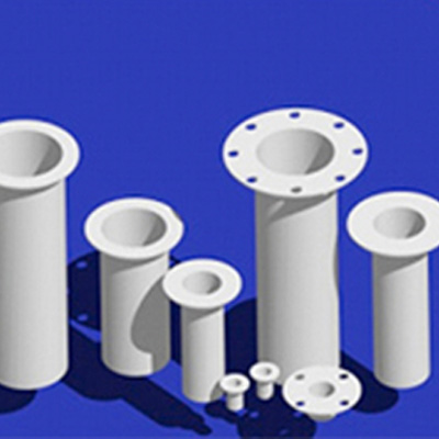
PTFE Nozzle Liner
3G PTFE nozzle liners provide protection for nozzles and manways on process vessels. They prevent chipping from insertion and use of dip pipes, thermal shock, instrumentation, or dropped or mishandled tools. They can also reduce scaling and build-up of solids. Also use them to protect surfaces of other lined or unlined nozzles from corrosive fluids, abrasive slurries, or erosive high velocity streams.
Check our tables of standard sizes. We also offer full-face units, and can make virtually any special size you need.
| DN | D1 mm | D3 mm | S mm | Lmax mm | PTFE SW |
| 1″ | 51 | 20 | 3.0 | 3000 | • |
| 1 ¼” | 54 | 28 | 3.0 | 3000 | • |
| 1 ½” | 73 | 32 | 3.0 | 3000 | • |
| 2″ | 92 | 41 | 3.0 | 3000 | • |
| 2 ½” | 105 | 56 | 3.5 | 3000 | • |
| 3″ | 127 | 66 | 3.5 | 3000 | • |
| 4″ | 158 | 94 | 4.0 | 3000 | • |
| 5″ | 186 | 117 | 4.0 | 3000 | • |
| 6″ | 216 | 139 | 5.0 | 3000 | • |
| 8″ | 270 | 182 | 6.0 | 3000 | • |
| 10″ | 324 | 231 | 7.0 | 3000 | • |
| 12″ | 381 | 288 | 7.0 | 3000 | • |
Nozzle Size
Standard liners fit nozzles from 1/2″ to 18″ pipe size. Special sizes available on request.
Length
Up to 4″ nominal pipe size, lengths available to 15 feet. Over 4″ nominal size, lengths available to 30″.
Flange Diameter
Minimum diameter of flange of standard liners corresponds to the raised face of ANSI Class 150 flanges. Full face or other special flange diameters available on request.
Thickness
Wall thickness of standard liners increases with liner size, from a minimum of 1/16″ wall up to 1/4″ wall. Nonstandard wall thickness available on request. Seal thickness equal to wall thickness standard, other seal thicknesses available on request.
End
Square cut end is standard. Diagonal cut available on request.
Nozzle Liner Worksheet
| Dimension | Description | Size |
| Required Data:_________________________________________________ | ||
| A | Sleeve O.D. (smaller than the nozzle I.D. by 1/8″ or more) | (max.—18″ pipe size) |
| B | Sleeve wall thickness | |
| C | Sleeve length (excluding flange) | (max.—30″) |
| D | Flange O.D. | (max.—21″) |
| E | Flange thickness | |
| Optional Data:_________________________________________________ | ||
| F | Diagonal cut | |
| G | Diagonal angle | |

